The normal discharge durations of 1, 2, 3, 4, 6, 8 or 12 months apply at an ambient temperature of 68°F (+20°C). Output and discharge durations will vary if the GREASOMATIC operates at a higher or lower temperature. The table below illustrates the output and discharge durations at varied temperatures.
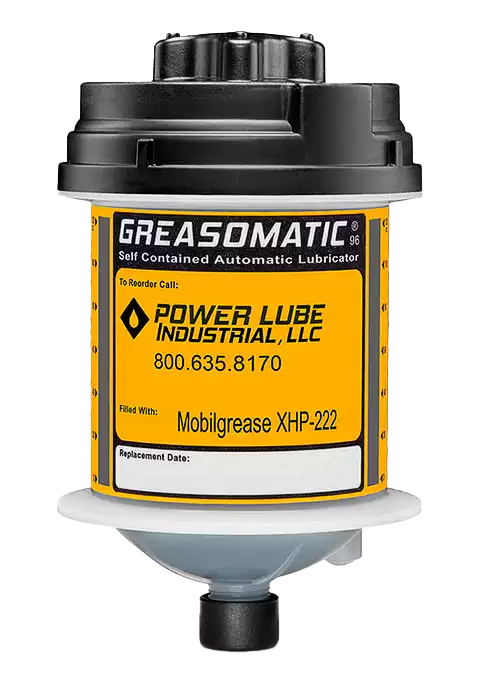
GREASOMATIC®96 KNOWLEDGE BASE
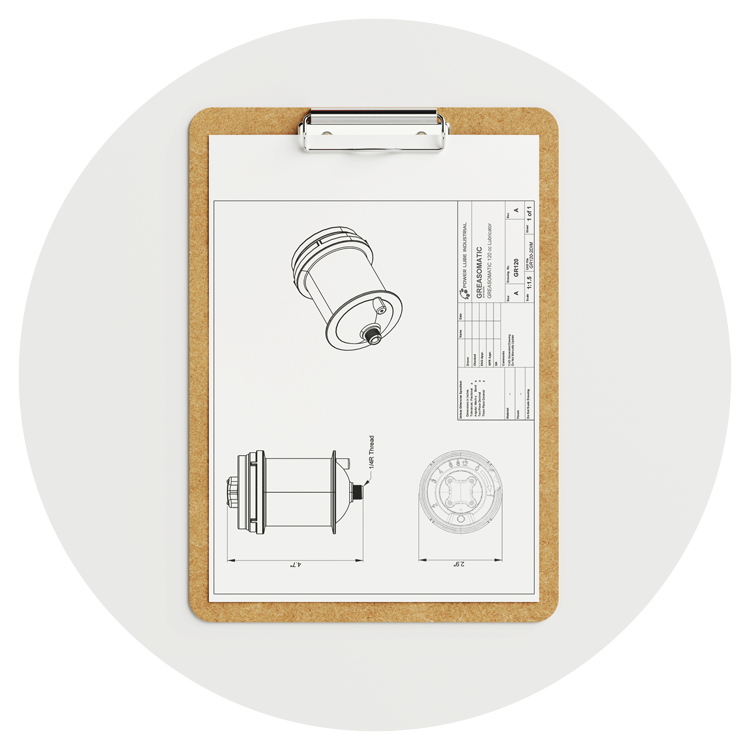
Dimensions


Settings
| Dial Setting | Daily Output | Discharge Period |
|---|---|---|
| 1 | 4 cc | 1 month |
| 2 | 2 cc | 2 months |
| 3 | 1.3cc | 3 months |
| 4 | 1 cc | 4 months |
| 6 | 0.7 cc | 6 months |
| 8 | 0.5 cc | 8 months |
| 12 | 0.3 cc | 12 months |
Average Ambient Temperature Chart
| Dial Setting | +32°F | +50°F | +68°F | +86°F | +104°F |
|---|---|---|---|---|---|
| 1 | 1 cc daily for 4 months | 2 cc daily for 2 months | 4 cc daily for 1 month | 8 cc daily for 0.5 months | Not recommended |
| 2 | 0.5 cc daily for 8 months | 1 cc daily for 4 months | 2 cc daily for 2 months | 4 cc daily for 1 month | 6 cc daily for 0.7 months |
| 3 | 0.3 cc daily for 12 months | 0.7 cc daily for 6 months | 1.3 cc daily for 3 months | 2.7 cc daily for 1.5 months | 4 cc daily for 1 month |
| 4 | 0.25 cc daily for 16 months | 0.5 cc daily for 8 months | 1 cc daily for 4 months | 2 cc daily for 2 months | 3 cc daily for 1.3 months |
| 6 | 0.2 cc daily for 24 months | 0.3 cc daily for 12 months | 0.7 cc daily for 6 months | 1.3 cc daily for 3 months | 2 cc daily for 2 months |
| 8 | Not recommended | 0.25 cc daily for 16 months | 0.5 cc daily for 8 months | 1 cc daily for 4 months | 1.5 cc daily for 2.7 months |
| 12 | Not recommended | 0.2 cc daily for 24 months | 0.3 cc daily for 12 months | 0.7 cc daily for 6 months | 1 cc daily for 4 months |
INSTALATION
Grease Installation
-
1
On first installation, use a hand grease gun and the same type of lubricant to pre-charge all fittings, lines and the bearing. The thread of the GREASOMATIC® is 1/4 BSPT and can be adapted for other thread sizes using standard adapters.
-
2
Activate Greasomatic (see below)
Oil Installation
-
A
Install the unit with the outlet in the up position and using a remote line to the bearing.
-
B
Install a check valve on the outlet of the GREASOMATIC® to prevent the oil from running out.
ACTIVATION
-
1

Turn the control knob clockwise so the arrow is pointing to the desired monthly setting. If you turn the control knob to far and pass your de- sired setting, you can turn the knob counterclockwise back to zero and start again.
-
2
Press the red button until it is flush with the top surface. Once the red button is pressed the discharge rate can not be changed.
-
3
Rotate the black control knob clockwise 10 to 12 turns. This releases the galvanic element into the liquid electrolyte, thus activating the GREASOMATIC®.

Specifications
| Housing Design | Plastic Body and Thread |
| Dimensions | 2.9" x 4.7" (74mm x 120mm) |
| Capacity | 120cc (4 oz) |
| Drive | Electrochemical |
| Electrolyte Liquid | Mildly Acidic Organic Acid |
| Temperature Range | 32°F to 140°F (0°C to 60°C) |
| Max Pressure Build-Up | 73 psi (5 bar) |
| Installation Thread | 1/4 BSPT (Adapters Available) |
| Discharge Period | 1, 2, 3, 4, 6, 8, or 12 months |
| Compatible Lubricants | Oil and Greases (up to NLGI2) |

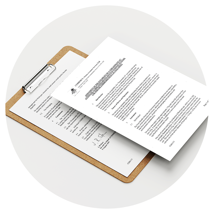

REGULATORY INFORMATION
| SYMBOL | Description |
|---|---|

|
Heart -1; Flammability -1; Reactivity -0; Special - - |

|
ATEX Directive 94/9/EC |

|
This product can be recycled. Please arrange for the environmental appropriate disposal of the lubricator. |

